Search results
Search for "back contact" in Full Text gives 18 result(s) in Beilstein Journal of Nanotechnology.
Mapping of integrated PIN diodes with a 3D architecture by scanning microwave impedance microscopy and dynamic spectroscopy
Beilstein J. Nanotechnol. 2020, 11, 1764–1775, doi:10.3762/bjnano.11.159

- back contact, is recorded using a logarithmic amplifier with a wide dynamic range [9][10]. Based on the measured current, the overall equivalent resistance, including the conductive tip resistance, the spreading resistance of the semiconductor under the contact, the bulk resistance of the sample, and
- the back-contact resistance [11], is experimentally determined. Therefore, at a fixed applied bias, the SSRM measurements map the variation in concentration of mobile majority carriers in doped semiconductors. A high load on the tip is required to obtain the spreading resistance. In fact, for silicon
- , an electrical back contact is created between the microscope chuck and the sample. Results and Discussion The vertical PIN structure Figure 2 shows the surface topography of the cross section of the PIN diode. The different materials used (silicon substrate, epitaxial layers, oxides, and alloy metals


Semitransparent Sb2S3 thin film solar cells by ultrasonic spray pyrolysis for use in solar windows
Beilstein J. Nanotechnol. 2019, 10, 2396–2409, doi:10.3762/bjnano.10.230

- -deposited Sb2S3 solar cells. An average visible transparency (AVT) of 26% of the back-contact-less ITO/TiO2/Sb2S3 solar cell stack in the wavelength range of 380–740 nm is attained by tuning the Sb2S3 absorber thickness to 100 nm. In scale-up from mm2 to cm2 areas, the Sb2S3 hybrid solar cells show a
- nontransparent 125 nm Ag back contact [21]. TiO2 is the most commonly used electron transport material (ETM) in Sb2S3 solar cells [18][25][26][27][28][29][30][31][32]. SnO2 and ZnO have also been employed as the planar ETM, with varying success [33][34]. Conjugated polymers, e.g., P3HT, Spiro-OMeTAD (2,2',7,7
- and back contact is needed to attain an AVT in excess of 20% for the complete solar cell. As-deposited Sb2S3 layers on glass/ITO/TiO2 substrate were amorphous (Figure 1d), as only signals of anatase-TiO2 and In2O3 from the substrate were detected by X-ray diffraction (XRD). In contrast, the XRD


CuInSe2 quantum dots grown by molecular beam epitaxy on amorphous SiO2 surfaces
Beilstein J. Nanotechnol. 2019, 10, 1103–1111, doi:10.3762/bjnano.10.110

- with the average size of the nanodots. Keywords: copper indium gallium selenide (CuInSe2); quantum dots; Introduction The chalcopyrite compound Cu(In,Ga)Se2 (CIGS) is used as the light absorber layer in thin film solar cells that typically consist of a glass substrate, a Mo back contact, the CIGS


Femtosecond laser-assisted fabrication of chalcopyrite micro-concentrator photovoltaics
Beilstein J. Nanotechnol. 2018, 9, 3025–3038, doi:10.3762/bjnano.9.281
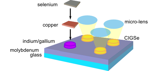
- state of the art. The electric back contact (molybdenum) covered with the highly-efficient light-absorber (CIGSe) on top is deposited on a carrier material (glass). A buffer layer (CdS), a window layer consisting of an intrinsic ZnO layer (ZnO) and an aluminum-doped ZnO layer (Al:ZnO) as transparent
- of 500 µm spacing. The optical micrograph on the left shows an array of laser spots on glass. The PVD of a 400 nm thick Mo back contact layer followed by indium island growth (at 500 °C substrate temperature and 0.3 Å/s indium deposition rate) led to an array of indium islands at the predefined
- in Figure 8. The laser was operated at 30 fs pulse duration and 800 nm center wavelength. Single laser pulses were focused on the glass–metal interface to transfer material from the donor substrate onto the molybdenum back contact of the future solar cell. The distance between donor and acceptor was


Near-infrared light harvesting of upconverting NaYF4:Yb3+/Er3+-based amorphous silicon solar cells investigated by an optical filter
Beilstein J. Nanotechnol. 2018, 9, 2788–2793, doi:10.3762/bjnano.9.260

- and ethanol for several times, and dried at 70 °C. The a-Si:H solar cell with an intrinsic p–i–n configuration was deposited on a 3 mm glass substrate by plasma-enhanced chemical vapor deposition. The front and back contact electrodes were deposited as AZO transparent conductive films. Then, the
- mixture containing NaYF4:Yb3+/Er3+ (0.6 wt %) and polymethylmethacrylate (PMMA, 10 wt %) was prepared in trichloroethane. One UC/PMMA layer was spin-coated on the back contact at 900 rpm for 60 s, heated at 120 °C for 1 h and slowly cooled down to room temperature. Finally, white paint was applied as back


Optimization of Mo/Cr bilayer back contacts for thin-film solar cells
Beilstein J. Nanotechnol. 2018, 9, 2700–2707, doi:10.3762/bjnano.9.252

- .9.252 Abstract Molybdenum (Mo) is the most commonly used material as back contact in thin-film solar cells. Adhesion of Mo film to soda–lime glass (SLG) substrate is crucial to the performance of solar cells. In this study, an optimized bilayer structure made of a thin layer of Mo on an ultra-thin
- chromium (Cr) adhesion layer is used as the back contact for a copper zinc tin sulfide (CZTS) thin-film solar cell on a SLG substrate. DC magnetron sputtering is used for deposition of Mo and Cr films. The conductivity of Mo/Cr bilayer films, their microstructure and surface morphology are studied at
- the back contact thickness to 600 nm. That is two thirds to half of the thickness that is currently being used for bilayer and single layer back contact for thin-film solar cells. We demonstrate the excellent properties of Mo/Cr bilayer as back contact of a CZTS solar cell. Keywords: back contact


Lead-free hybrid perovskites for photovoltaics
Beilstein J. Nanotechnol. 2018, 9, 2209–2235, doi:10.3762/bjnano.9.207

- are withdrawn to the Spiro-MeOTAD HTL and then – into the gold back contact (Figure 11b). The charge separation efficiency is evidenced by a relatively high FF of almost 80%, while a high Voc of 0.83 V observed for such cells attests to the structural perfection of the light-absorbing HP layer [84]. A
- similar Voc (0.895 V) was reported for a MABI-based cell produced without HTLs with a single carbon back contact [86]. In this case, a top light conversion efficiency was only 0.054% (Table 1), indicating the crucial role of the hole transfer dynamics for the total cell performance. The efficiency of MABI


Spin-coated planar Sb2S3 hybrid solar cells approaching 5% efficiency
Beilstein J. Nanotechnol. 2018, 9, 2114–2124, doi:10.3762/bjnano.9.200

- transmitted to the metal back contact where it is reflected back through the P3HT into the Sb2S3 absorber where it contributes to the photocurrent. The decreased parasitic absorption above 650 nm causes a maximum in the EQE at roughly that wavelength. KP115 on the other hand still absorbs at 650 nm so that


Localized photodeposition of catalysts using nanophotonic resonances in silicon photocathodes
Beilstein J. Nanotechnol. 2018, 9, 2097–2105, doi:10.3762/bjnano.9.198

- the electrolyte, which was illuminated through a quartz window. The electrolyte consisted of an aqueous solution of chloroplatinic acid (4 mM) and Na2SO4 (0.1 M), with the pH value adjusted to 11 with 2 M NaOH. The back contact of the sample consisted of 4 nm of chromium and 50 nm of gold deposited


A scanning probe microscopy study of nanostructured TiO2/poly(3-hexylthiophene) hybrid heterojunctions for photovoltaic applications
Beilstein J. Nanotechnol. 2018, 9, 2087–2096, doi:10.3762/bjnano.9.197

- detection range within 100 fA to 1 µA. Silicon tips coated with a PtIr conductive alloy (PPP-CONTPt from Nanosensors) were used. The tip and the back-contact were connected while the sample was locally irradiated from the bottom (through the patterned ITO–glass substrates) under AM 1.5 calibrated white


Synthesis of graphene–transition metal oxide hybrid nanoparticles and their application in various fields
Beilstein J. Nanotechnol. 2017, 8, 688–714, doi:10.3762/bjnano.8.74

- charge transfer [209]. The graphene layer, acting as an oxidation resistance layer, fills the open space by a conductive and transparent film and it protects the NWs from the harsh environment [210]. Cu NW–graphene has been used as the back contact in thin film CdTe solar cells giving a solar efficiency


Sb2S3 grown by ultrasonic spray pyrolysis and its application in a hybrid solar cell
Beilstein J. Nanotechnol. 2016, 7, 1662–1673, doi:10.3762/bjnano.7.158

- at a distance that was adjusted by using a calibrated silicon solar cell as the detector. The active area of the solar cells is defined by the back contact area of 1.7 mm2 or 1 cm2. The total transmittance spectra of the layers and solar cells were measured in the wavelength range of 300–1500 nm on a


Entropy effects in the collective dynamic behavior of alkyl monolayers tethered to Si(111)
Beilstein J. Nanotechnol. 2015, 6, 583–594, doi:10.3762/bjnano.6.60

- ][40]. An ohmic back contact was obtained by applying a silver paste electrode on the scratched Si rearside and a mercury top electrode (99.999% Fluka, contact area S = 5 × 10⁻³ cm2) was used to avoid electrical shorts through possible pinholes in the OML. A solid Hg electrode is obtained in the low
- , useful information on dipolar mechanisms is limited by the series resistance RS (due to bulk Si and back contact resistance). Acquisition of dipolar relaxation data was performed in the reverse bias regime of the rectifying metal/OML/Si junction, with decreasing temperature steps and, at each temperature


Low-cost plasmonic solar cells prepared by chemical spray pyrolysis
Beilstein J. Nanotechnol. 2014, 5, 2398–2402, doi:10.3762/bjnano.5.249

- , the scattering medium must have a lower refractive index than that of the absorbing medium. As required, the refractive index of Au is in the range 1.5–0.2 [18] and that of CuInS2 is 3–2.6 [19] in the wavelength range of 400–900 nm. It cannot be entirely excluded that charge transfer at the back
- contact region (graphite/gold/CuInS2) was improved with respect to the reference (graphite/CIS). However, resonant absorption peaks in the red/infrared region would not be expected to emerge (Figure 4) in the case of the charge transfer argument. For the solar cell prepared by spraying 2.5 mL of the Au


Photodetectors based on carbon nanotubes deposited by using a spray technique on semi-insulating gallium arsenide
Beilstein J. Nanotechnol. 2014, 5, 1999–2006, doi:10.3762/bjnano.5.208

- spray technique to deposit the nanotube film. Two different configurations have been analysed. The first with a Ti/Au back contact (SFS) and a CNT film on the other face. The second with CNTs on both sides (DFS). Furthermore an ITO/GaAs/Ti/Au device was prepared to better understand some experimental


Biomolecule-assisted synthesis of carbon nitride and sulfur-doped carbon nitride heterojunction nanosheets: An efficient heterojunction photocatalyst for photoelectrochemical applications
Beilstein J. Nanotechnol. 2014, 5, 770–777, doi:10.3762/bjnano.5.89

- photoelectrode, which can be attributed to the large contact area between the CN/CNS photoelectrode and the electrolyte as well as an appropriate band alignment of the CN/CNS interface. It has been well-established that photocurrent is generated because of the diffusion of photogenerated electrons to the back
- contact and the simultaneous consumption of photogenerated holes by the hole acceptor in the electrolyte. As such, the superior photocurrent of CN/CNS heterostructure indicates the more efficient charge carrier separation and longer lifetime of the free charge carriers. A control experiment using


Structural, electronic and photovoltaic characterization of multiwalled carbon nanotubes grown directly on stainless steel
Beilstein J. Nanotechnol. 2012, 3, 360–367, doi:10.3762/bjnano.3.42

- photovoltaic device. The Schottky junction between the Si and the MWCNT film is the photoactive junction. Steps of SiO2 (300 nm) are used to avoid a short-circuit forming between the silver paint (top electrode) and the silicon substrate. The back contact is made of aluminium. In the in-plane geometry, the
- switch T1 is on and T2 is off; and vice versa in the top-down configuration. As a result, the photocurrent is collected at the MWCNT film in the former case, and at the MWCNTs and Si (back contact) in the latter. External quantum efficiency (EQE) spectra obtained in the top-down (dotted curve) and in
- one is formed at the back contact between Si and Al, i.e., a hint of a non-ohmic contact. (d) Detail of (c) in the most meaningful zone, i.e., in the fourth quadrant of the J–V characteristic. Schematic depiction of the airbrush deposition process. A solution of MWCNTs in isopropyl alcohol was


Junction formation of Cu3BiS3 investigated by Kelvin probe force microscopy and surface photovoltage measurements
Beilstein J. Nanotechnol. 2012, 3, 277–284, doi:10.3762/bjnano.3.31

- with Al, deposited by dc magnetron sputtering [21]. For analysis by Kelvin probe force microscopy (KPFM) [7], surface photovoltage (SPV), and X-ray photoemission spectroscopy (XPS), sample contact was established at the Al back contact. CdS thin films were deposited onto the Cu3BiS3 layers from a


